Coded information can be stored in many different ways. In addition to mechanical, magnetic and electronic storage, a conventional type of storage has also become established, not least due to the further development of optical reading systems – the barcode (also known as the barcode). Barcodes are based on the binary principle, which is represented by a certain number of wide and narrow parallel bars and gaps. There are various barcodes, which differ in their form of representation (number and width of bars). The sequence of this structure results in a defined numeric or alphanumeric statement. Especially in the transportation and warehousing sector, where many different items are marked and managed, this type of data presentation is often superior to other systems.
Structure of a barcode and advantages of barcode systems
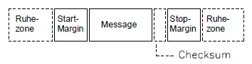
A barcode is divided into different areas: The blank zones are unprinted areas before and after the actual barcode. They are usually white. The rule of thumb for the width of these zones is:
- at least five times the width of the widest bar (Datalogic, a scanner manufacturer)
- At least ten times the narrowest bar (SICK, a sensor manufacturer)
The start character (start margin) is a special bar/gap combination. It is always in the first position of the code. When this character is detected, the decoder begins to process the impulse train of the scanner. The start character is also used for security purposes. It signals to the system that a barcode symbol is actually being received and not some sequence of reflected extraneous light.
The stop character (stop margin) is also a serial character. It signals the end of the code. The decoder is thus informed that the complete code has been received, then it checks and translates the message. To make a code readable from both sides, start and stop characters are not symmetrical. If the code is read from the “wrong” direction, the decoder recognizes this and converts the character string internally. The message contains the actual information.
The code type determines the syntax. The checksum is an optional character and is defined for most code types. It is used to check the plausibility of the read code.
Barcode systems have numerous advantages, which include the following:
- quick data entry
- elimination of errors due to keyboard entry or data manipulation
- flexible and fast creation of data carriers (labels)
- cost effective data carrier medium
- combinable together with plain text on one data carrier
Overview of different barcode types
There are a large number of different code types, some of which are also used on a manufacturer-specific basis. The four most important types for material flow systems in intralogistics are listed in the following table. These can be processed by most reading systems or decoders from the various manufacturers and are therefore referred to as standard codes.
| Standard code | Information carrier | Zeichenvorrat | Vor- und Nachteile |
|---|---|---|---|
| 2/5 Industrial | Only the bars (5 bars = 1 character) | Digits 0-9 | + Easily readable + Easily printable - Low information density (3.9 mm/digit with min. width 0.3 mm) |
| 2/5 Industrial | Bars and gaps (5 bars or 5 gaps = 1 character) | Digits 0-9 | +High information density (2.3 mm/digit at min. width 0.3 mm) - Low printing tolerances +/- 10% |
| Code 39 | 5 bars and 4 gaps per character (one wider gap = character spacing) | Digits 0-9 Letters A-Z 7 special characters |
+Alphanumeric representation - Low printing tolerances +/- 10% - Low information density (4.8 mm/digits with min. width 0.3mm) |
| Code 128 / EAN 128 | 3 bars and 3 gaps per character (1 character consists of 11 elements) | ASCII character set | +Alphanumeric representation +High information density + high reading reliability - not widely used - high demands on the printing technology |
Barcode label and barcode system
The scanning process of a barcode usually takes place over the entire bar height. This results in multiple sweeps of the code. Problems occur mainly with heavy staining, damage to the code, or poor lighting conditions (insufficient/interfering light).
The most common cause of reading errors, however, is the poor print quality of the barcode label. The better the print quality, the better and more reliable the readability of the code. As a result, the first-read rate increases and the risk of misreading due to substitution with a different bar/gap sequence decreases.
To achieve the best possible readability, printing on code labels should meet the following quality criteria:
- Compliance with the dimensions and tolerances according to the code specifications.
- If possible, no spots or gaps (a spot of a certain size in a gap is recognized by the scanner as a narrow element)
- Minimum edge roughness (the code bars should present sharp and uniform edges as much as possible)
- High contrast ratio and sufficient reflectivity (good reading reliability with black strokes on a white background)
Physical requirements for the label are:
- Good adhesion of the ink and the label
- Resistance to oil and chemicals
- resistance to wear
- as lightfast as possible (no yellowing)
Today’s readers are mostly laser scanners or image processing cameras (CCD cameras). For error-free detection of a barcode, a minimum contrast between bars and background is necessary for the code to be recognized correctly. This contrast is a dimensionless quantity and has been defined as print contrast signal (PCS) according to DIN 66236.
The PCS is calculated according to the following formula:
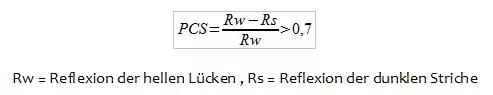
The best contrast is obtained with white background and black strokes. In some cases, dark green or dark blue lines can be printed on a pastel background. However, special red light illumination (for example, laser scanner in the red range at 600 – 632 nm) is then necessary for reliable reading.
Basic elements of a barcode system
In addition to the scanner, other basic elements are needed to handle barcodes in material handling systems. These elements are:
- The printer creates the bar code. The code is either printed directly on the packaging or attached to the product or a transport aid.
- The sensor scans the coded information optoelectronically. It receives the diffusely reflected light of the line/gap sequence and converts the light/dark sequence into electrical signals.
- The decoder (also decoder, reader) converts the electrical signals of the sensor into a digital pulse sequence and evaluates it with the help of a microprocessor. The decoded characters can be displayed and made available for data transmission via a serial interface for the respective higher-level data processing system.
- The computer receives the sent data logs, processes them independently, or forwards them. Here, only relevant data for the control of the material flow is passed on to the transport control system.
The code density of barcodes
In connection with code quality, the terms high-, medium- and low-density appear repeatedly. They denote the code density.
Code density is differentiated according to the minimum bar thickness:
- Ultra High-Density code (minimum line thickness < 0.19 mm)
- High-Density code (minimum line width 0.19 mm – 0.24 mm)
- Medium-Density code (minimum line width 0.24 mm – 0.30 mm)
- Low-Density code (minimum bar thickness 0.30 mm – 0.50 mm)
- Use at long distances (minimum bar thickness > 0.50 mm
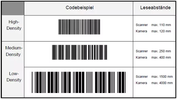
Together with the selected line width ratio, this results in a more or less high information density (character/inch or character/millimeter). Ultimately, the reading distance is decisive for the selection of the line width.
Barcode self-verification
There are codes that are verifiable due to their structure. Most barcodes have a so-called self-verification to increase the reading reliability.
With this type of barcode, for example, the number of thin and thick bars per digit is the same or each character contains exactly 2 wide bars (so-called 2/5 codes). Due to this specification, a plausibility check is possible by simply counting the bars.
Further security of the reading is achieved by the use of a check digit (checksum). The check digit is represented by an additional digit immediately before the stop character of the code. If this scanned check digit does not match the digit calculated by the decoder, the code is not transmitted.
Check digit calculation according to Modulo 10
Modulo 10 is a widely used method to perform a verification of identification numbers.
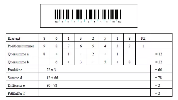
a) Cross sum of all digits with odd position number
b) Cross sum of all digits with even position number
c) Multiplication b by the factor 3
d) Sum of a + c
e) Difference of d to the next multiple of 10
f) The result e is the checksum PZ
Barcode terminology
The essential elements and terms related to barcodes:
-
- Barlines:
Dark elements of a barcode. - Gaps:
Light elements of a barcode. - Barcode (barcode):
A defined number of parallel, alternating bars and gaps. - Start and stop characters:
Each code begins with a start character and ends with a stop character. Furthermore, the start and stop characters can be used to determine the code type. - Discrete code:
A barcode that is formed only from bars of different thickness. The gaps are the same width and do not contain any information (eg 2/5 Industrial). - Continuous code:
In addition to the bars of different widths, the gaps of different widths are also used as information carriers (eg 2/5 Interleaved). - Blank zone:
Unprinted free space before the start and after the stop sign. This zone is necessary to signal the reader code start and code end. - Self-checking code:
Makes it possible to independently detect errors during reading, according to a predetermined algorithm. However, substitution errors can not be completely ruled out.
- Barlines:
Bar width ratio:
Ratio of wide bar (gap) to narrow bar (gap) in a code.
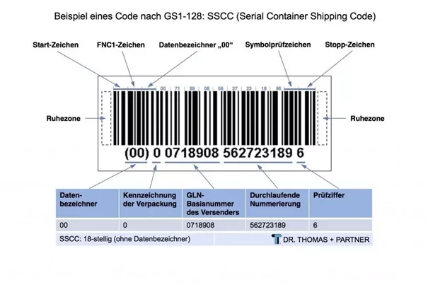
Barcode-Standards – EAN, GTIN und GS1-S
The most widely used barcode is the EAN code (European Article Number), which was designed for the European food trade in 1976. The aim of the EAN was to ensure unique identification of inventories throughout Europe. After only a few years, EAN coding was also used in Asia, Africa, Australia and South America. In 2002, the globally active umbrella organization EAN was merged with the North American UCC (Uniform Code Council) to form today’s GS1 (Global Standards 1). Accordingly, a new term was to be established for the compatible identification systems EAN and UPC (Uniform Product Code): GTIN (Global Trade Item Number). GS1 expects this to lead to a globally unique identification of articles and services.
Even during production, the GS1 standard is an integral part of the value chain. Thus, already during procurement and during the manufacturing of products, each individual item as well as the product itself is marked with a Global Trade Item Number, GTIN for short (unique item number). This is followed by information for further processes such as storage, transport, delivery, trade and return. They are all usually stored together on the code variant “GS1 standard 128“. Each item is thus given a distinctive label that identifies it within a particular packaging hierarchy.
Advantages GS1 Standard:
-
- Fast acquisition at goods receipt or in the middle of the material flow
– Flexible and fast creation of data carriers and labels
– Cost-effective data carrier medium
– Can be combined with plain text together on one data carrier
– 16. 000 or more scans per second, at a conveyor speed of 2.3 meters per second
– Proven error-free barcode capture
– Fewer manual processes, more automation
– Data reconciliation at a capture station in real-time
- Fast acquisition at goods receipt or in the middle of the material flow
.
Comparison of RFID and barcode in retail
Marking a product with a barcode has become widely accepted for automatic identification of inventory in retail. The barcode is cheap, reliable and easy to produce compared to other possible markings. The successor to the common barcode is the RFID chip.
Both technologies are compared in the following table.
| Parameters | Barcode | RFID |
|---|---|---|
| Typical data volume | 1 to 100 B | 16 to 64 kB |
| Data access | "Write-Once" + "Read-Only" | "Read-Only / "Read and Write" |
| Direction of communication | One direction | bidirectional |
| Data transmission | optical | Radio transmission in the HF, VHF or UHF range |
| Max. Distance between data carrier and reader | 0-5 m with visual contact | 0-100 m without visual contact strongly dependent on frequency and power supply |
| Technical interference factors | Dirt, damage, optical cover | Interference of radio transmission by metals and liquids |
| Bulk acquisition | not possible | possible |
| Read confirmation | yes | yes |
| Multiple data descriptions | not possible | possible |
| Theft protection | not possible | possible |
| Marking costs | low | medium/high |
As can be seen from the table, there are some limitations for barcode technology that do not apply to RFID technology. According to this, RFID systems are superior to barcode technology (which will be described in detail in another article). This refers primarily to the advantageous storage possibilities and to factors that have to do with environmental influences. These include, for example, dirt, moisture and optical covers.
In stationary retail, in addition to the functionalities of RFID, the focus is on cost-effectiveness. The disadvantages of RFID transponders compared to barcodes are the higher costs and the necessary investments for the required hardware and software of RFID systems.
Summary
Bar codes, also called bar codes, are binary codes that consist of an array of parallel bars and separator gaps. These are arranged according to a predetermined image and are interpreted as a specific character or sequence of characters. The reading can be done with a laser scanner. In this process, the different reflection of a laser beam on the black lines and white gaps is evaluated. The reading can also be done using a CCD (charge-coupled device) reader. The CCD reader is designed like a barcode camera with a CCD line. Here, the code is imaged with sufficient contrast on the CCD line and evaluated.
The development of barcode reading systems and the improved printing technology of the labels have led to the fact that one can mark each product or conveying equipment and achieve a specific control of the material flow via the assigned number (order or part number). The state of the art today is that product data can be scanned in bar-coded form at a read rate of up to 500 scans/sec. as it passes by. With appropriate lenses, a depth of field of up to 1500 mm is possible.
Processing the data with the computer systems available today enables flexible control of transport and storage orders. In conjunction with a database, the production volume can be called up at any time. At the same time, every operation that has been carried out is documented. Barcodes are widely used worldwide in different variants and international standards. They have established themselves as a very practical method of identifying articles (article numbers). In some cases, however, barcodes are being superseded by RFID technology.
Other articles you might also be interested in:
Also available in Deutsch (German)